|
| Board |
Manufacturer & Product Number |
Description |
|---|---|---|
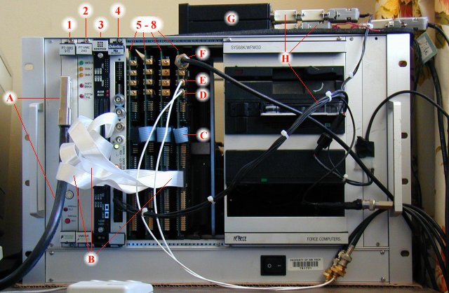
| 1 |
Performance Technologies PT SBS-915 |
This is an interface board which allows a host computer equipped with an S-Bus adapter to communicate with the VME boards (especially the DSP board). |
| 2 |
Performance Technologies PT VME-240 |
This is a 32 MB memory board which is currently only used for the triggered interferometer mode. In this mode, interferometer data is block-transferred almost continuously between the DSP and the memory board. Unfortunately, the VME bus must be locked for these transfers, which forces a data acquisition dead time after a trigger is completed since the transfers must be disabled in order for the host computer to gain access to the VME bus and the data. |
| 3 |
Sonitech Technologies SP-40 Dual DSP |
This is essentially the "brains" of the entire system. The dual DSPs process the data real time and make the crucial decisions on which data should be stored and which should be discarded. The DSPs are Texas Instruments C40 processors which run at 40 MHz (slow by comparison to todays CPUs, but they are computationally efficient). Each of the 2 DSPs has it's own dedicated memory area. The DSPs are linked to each other through an external communication port (see "B" description below) which is configured for bidirectional communication between the DSPs. |
| 4 |
KSI Odetics GPS VME |
This board interfaces to a GPS Lowrance receiver. The board phase locks to the GPS and outputs time codes which are accurate to within 1 microsecond of actual universal time (UT). The time codes are output onto the VME P2 connector and are intercepted by each A/D board, which mixes the time codes in with the data stream (see "5-8" below). |
| 5-8 |
New Mexico Tech Analog/Digital (A/D) boards |
The inputs of these analog/digital conversion boards
interface directly to the voltage output of electric
field, log-RF, sine/cosine phase, etc.. and convert
these voltages to digital values. Most of the inputs
are configured for 8-bit conversion, but some of them
can be (and have been) reconfigured for higher
precision 12-bit sampling (see "D" and "E" below). The
boards sample data continuously and can be configured
(jumpered) for either 500 kHz or 1 MHz sample rates.
The boards arrange the digital data into 100
microsecond data blocks, the beginning of which is
always time-stamped with GPS time codes. The most
common use for each individual board is listed below:
|
| Item | Name | Description |
|---|---|---|
| A | S-BUS cable |
A 25' long cable which connects the VME crate to a host (Sun) computer. The host computer controls the DSPs and retrieves data through this cable. |
| B | ASM-C cables |
High speed cables which connect each A/D board to a COM port on either the upper or lower DSP. The A/D boards output digitized data and time codes through these cables. The DSPs can also reset and synchronize the A/D boards through these cables. |
| C | A/D board cable |
This cable interconnects the A/D boards. One A/D board is configured as the master and synchronously controls the other slave boards through this cable. This arrangement insures that data is sampled synchronously. |
| D | Fast Antenna input |
This is an input for a 12-bit A/D converter. Normally, fast antenna electric field data is the input source. Whatever data is input here becomes the trigger source for the sferic data acquisition mode. |
| E | Slow Antenna input |
This is an input for another 12-bit A/D converter. Normally, slow antenna electric field data is the input source. |
| F | log-RF input |
This is an input to an 8-bit A/D converter. Normally, the interferometer log-RF (274 MHz) is the input source. In RF-thresholded interferometer mode, this data is the trigger source. |
| G | Horita GPT-50 unit |
The Horita unit(s) are actually not integrated into the VME system, but usually must be in close proximity in order to use the GPS output (see H below). The Horitas, one of which is shown above (viewed from the side), inserts GPS timing information onto video. |
| H | GPS serial cable |
GPS information obtained by a Lowrance receiver passes through the Horita unit(s) down into the KSI Odetics GPS VME board. The numerous connectors on the back of the Horita unit are combinations of gender changers, null modem adaptors, and a custom 1 PPS video pulse insertion adaptor. |
This web page was last modified on March 26, 2001
by Mark Stanley