The following shows the most recent plans for deploying the New Mexico Tech 3-dimensional Lightning Mapping Array (LMA) during STEPS, based on a second field trip to the project area during the week of March 13-19, 2000. The purposes of this trip were to identify additional sites for the mapping stations, and to test the possible sites for RF noise levels (primarily from local power lines and transformers). The network is now close to its final configuration, with all but the two northeastern stations having been arranged with the landowners. We will continue to evaluate the configuration up until the time of deployment, however, beginning shortly after May 1.
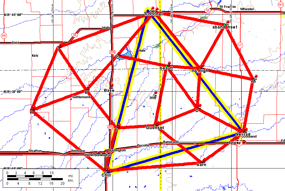
The figure below shows the planned locations of the stations relative to the triple Doppler network. The blue-yellow triangle indicates the locations of the radars, with the CSU Chill radar being located at the Kit Carson County Airport just south of Burlington, CO and the NCAR S_Pol radar near the CO-KS border east of Idalia. The third radar is the Goodland NEXRAD on the SE part of the network. We will have mapping stations close to each these locations and at the other indicated locations. The network has a total of 15 stations, five more than we have used in previous studies. One of the stations, probably the one near the NWS office in Goodland, will be provided by Global Atmospherics in Tucson, who operate the National Lightning Detection Network. The remainder will be Tech systems - 10 of our original stations operated in Oklahoma and New Mexico and 4 new stations which incorporate version 2 of the mapping electronics, being developed for NASA Marshall Space Flight Center in Huntsville, Alabama.
Figure 1. The Lightning Mapping Network.
In addition to providing concentrated coverage within the triple Doppler triangle, the network is configured to ensure good coverage in the dual-Doppler lobe of the CHILL and S-Pol radars, namely outside the western part of the triple Doppler triangle, as well as in the northeastern dual-Doppler lobe. Both lobes are typically good areas for storms, according to NWS office personnel. It would be good to also better cover the southern dual-Doppler lobe, and we will be considering how to improve this. The system will provide three-dimensional coverage for an extended area several tens of kilometers outside the network an any case.
At ten of the stations we will measure and record the atmospheric electric field (with field mills) and lightning electric field changes (with a slow antenna). This will be done continuously in time, with the slow antenna sampled probably at a 5 kHz rate. Fast electric field change waveforms produced by lightning will be recorded on a triggered basis at three of the lightning mapping sites. The fast field measurements will be made at the Burlington Airport and NWS sites, which have buried power lines in their vicinity. The third will probably be at the lightning mapping site near S-Pol to provide a triangular array of fast antenna stations essentially the same as the triple Doppler triangle. Fast electric field measurements will also be made at the interferometer site, discussed below, providing a total of 4 fast DeltaE measurements. These measurements should enable us to clearly identify the occurrence and location of - and + CG strokes, and potentially enable fast in-cloud events to be located as well.
The Tech Lightning Interferometer will be operated near the center of the LMA, tentatively at the location identified as `Intf'. This location is about 275 km ESE of Yucca Ridge, where sprite observations will be made. Among other things, the interferometer will show the paths of fast dart- and K-streamers that propagate along the main channels of IC and CG discharges. Fast electric field and slow antenna data will also be recorded at the interferometer site.
Shown below are the communications links to the LMA stations. The purposes of the links are to allow the stations to be remotely monitored and controlled, and to enable some of the observations to be processed and displayed in real time. We are putting substantial effort into developing the real-time capability and the pieces are starting to come together. (In any case, the primary data recording will be on DAT tapes at each site, as we currently do.) The yellow-magenta links will be high-speed (1-2 MBit/sec) ethernet connections using 2.4 GHz wireless communications and form a trunk for coupling in the data from the remote sites. The remote site data will be coupled into the trunk via 915 MHz 115 kBaud wireless modem links, shown in green. A similar communications system has been used to monitor and control the network in New Mexico for two seasons now, and has been robust and trouble-free. The STEPS communications links will be over rolling hills and flatter ground than in NM, which will make it more difficult to establish some of the links.
The trunk will feed into a tower on the west edge of Goodland, from which there will be a short hop to our base of operations in office trailers outside the National Weather Service office. (The same tower is being used as the repeater site for the radar and mobile balloon VHF radio nets.) Our main computer facilities will be at the NWS location, and will be used for monitoring and controlling the network and for data processing.
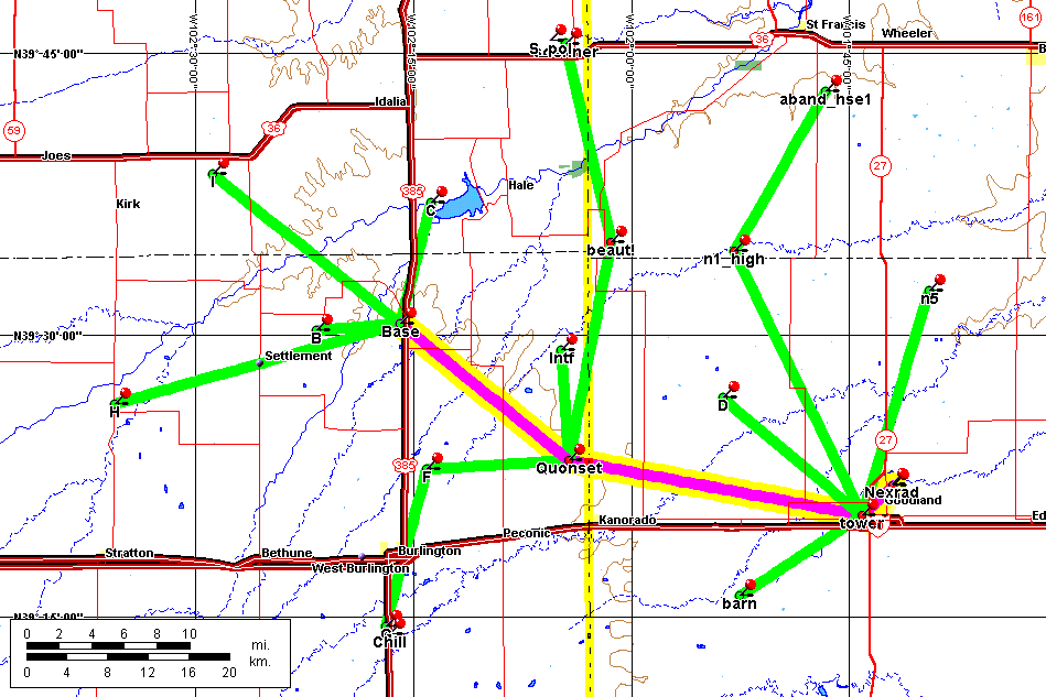
Figure 2. Communications links for the Lightning Mapping Array. The yellow-magenta links will be wireless ethernet links at 2.4 GHz and will provide a trunk for connections to the remote stations. The latter, shown in green, will be via 915 MHz wireless modems.