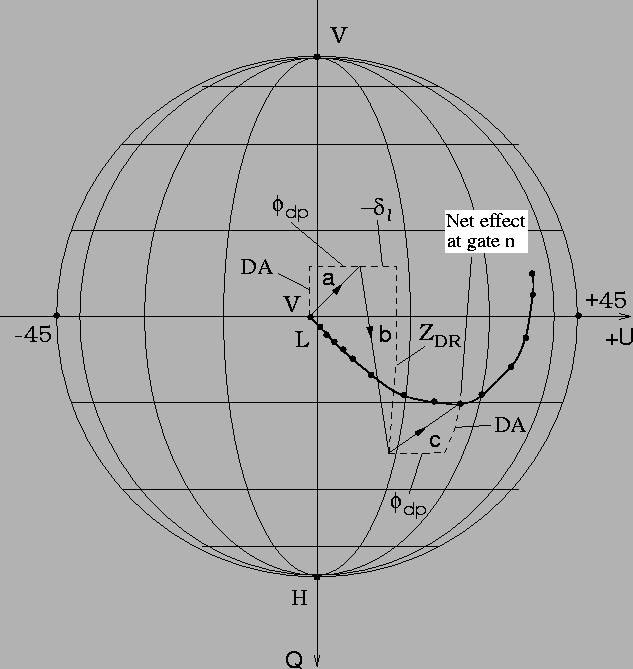
Figure 6 shows how the depolarization effects combine to produce the measured radar signals. To illustrate this we assume that the depolarization is due to horizontally aligned particles, both during propagation and backscatter. The radar is assumed to transmit a signal having approximately equal H and V powers; for simplicity we assume the transmitted polarization to be LHC. The results are applicable whether the H and V signals are transmitted simultaneously or on alternate pulses.
In propagating from the radar to the scattering volume, the signal
experiences the combined effects of differential attenuation (DA) and
differential propagation phase, ![]() .
These cause the polarization
state respectively to move upward toward the V polarization point and
to the right toward the
.
These cause the polarization
state respectively to move upward toward the V polarization point and
to the right toward the
![]() point (segment a). Upon backscatter,
the polarization state is abrubtly displaced downward by the differential
reflectivity
point (segment a). Upon backscatter,
the polarization state is abrubtly displaced downward by the differential
reflectivity
![]() of the scatterers and to the right by any differential
backscatter phase
of the scatterers and to the right by any differential
backscatter phase
![]() .
In propagating back to the radar the signal
experiences additional differential attenuation and differential phase.
Not depicted in the figure is the effect of the shape correlation f in
reducing
.
In propagating back to the radar the signal
experiences additional differential attenuation and differential phase.
Not depicted in the figure is the effect of the shape correlation f in
reducing ![]() and therefore the degree of polarization of the signal.
and therefore the degree of polarization of the signal.
 |
The radar observes the net effect of the above changes as a single point corresponding to the particular volume of scatterers. The returns from other range volumes will have their own net polarization states. The sequence of the polarization states versus range forms a trajectory, as indicated. The trajectories shown in the data plots of the previous section are produced in this manner and include not only the effect of horizontally aligned particles but of other classes of particles, as discussed below.