The alignment direction observations illustrate the relation between linear
and circular polarization measurements, as we now discuss. Measurements in
a circular polarization basis are characterized by the covariances W1=
WL, W2= WR, and
W = WLR. Rather than work with the rationalized
quantities WL/WR and
![]() ,
as is convenient in a
linear polarization basis, circular polarization measurements are better
characterized by the quantity W/W2, where W2 is the co-polar return.
This is because W/W2 better reflects the meteorological parameters being
measured than the WL/WR or
,
as is convenient in a
linear polarization basis, circular polarization measurements are better
characterized by the quantity W/W2, where W2 is the co-polar return.
This is because W/W2 better reflects the meteorological parameters being
measured than the WL/WR or
![]() do. The W/W2 approach was
formulated by Barge (1972), Humphries (1974), and McCormick and Hendry (1975),
who derived expressions relating W/W2 to the polarization characteristics
of the propagation and scattering medium. The relations have formed the
basis for interpreting circular polarization measurements in a number of
studies (e.g., McCormick and Hendry, 1975, 1979; Hendry and Antar, 1984;
Bringi and Hendry, 1990; Metcalf, 1995, 1997); Krehbiel et al., 1996) but
are conceptually and analytically difficult to understand. It has also been
difficult to understand how circular and linear observations are related, or
how well quantities such as
do. The W/W2 approach was
formulated by Barge (1972), Humphries (1974), and McCormick and Hendry (1975),
who derived expressions relating W/W2 to the polarization characteristics
of the propagation and scattering medium. The relations have formed the
basis for interpreting circular polarization measurements in a number of
studies (e.g., McCormick and Hendry, 1975, 1979; Hendry and Antar, 1984;
Bringi and Hendry, 1990; Metcalf, 1995, 1997); Krehbiel et al., 1996) but
are conceptually and analytically difficult to understand. It has also been
difficult to understand how circular and linear observations are related, or
how well quantities such as
![]() and
and ![]() can be determined from circular
polarization measurements (e.g., McCormick, 1979; Torlaschi and Holt, 1993).
For this reason many meterological radars have used linear polarization.
can be determined from circular
polarization measurements (e.g., McCormick, 1979; Torlaschi and Holt, 1993).
For this reason many meterological radars have used linear polarization.
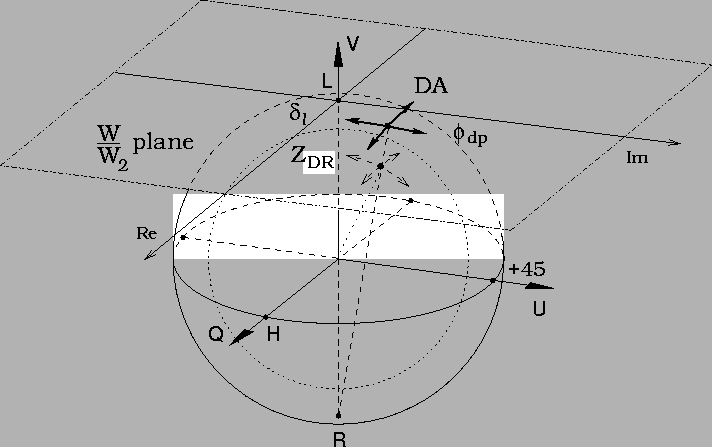
The Poincaré sphere approach provides a good way of showing how circular and linear polarization measurements are related. In particular, W/W2represents a stereographic projection of the polarization state onto a plane tangent to the Poincaré sphere (Scott, 1999). This is illustrated in Figure 9. The plane is tangent at the copolar circular polarization point (considered for simplicity to be LHC) while the projection is from the orthogonal polarization point (RHC). Because W2 corresponds to the total signal power (polarized plus unpolarized), both the tangent and the projection points are on the surface of the outer, total power sphere, while the polarization state itself is on the inner, Poincaré sphere (see Figure 4).
 |
The above picture shows why W/W2 has been a useful quantity in circular
polarization measurements; the depolarization effects of horizontally
aligned particles produce nearly orthogonal motions in the W/W2 plane.
Also, the depolarization produced by non-horizontally aligned particles
is simply rotated from that produced by horizontally aligned particles.
From Figure 8, the polarization changes due to particles
aligned at an angle ![]() are rotated by an angle
are rotated by an angle ![]() in the W/W2plane. The latter has formed the basis for determining alignment directions
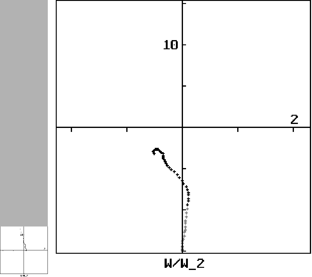
using the W/W2 approach. Differential propagation phase due to horizontally
aligned particles causes upward motion of W/W2, in the positive imaginary
direction (Figure 10a), while that due to vertically aligned
particles causes downward motion in the negative imaginary direction (Figure
10b). The Poincaré projection plots seen in the data figures of
this paper are similar to W/W2 plots in that they view the Poincaré sphere
from above. The trajectories due to horizontally and vertically aligned
particles (e.g., Figures 2 and 15) are essentially the
same as would be obtained in W/W2 space, except rotated by
in the W/W2plane. The latter has formed the basis for determining alignment directions
using the W/W2 approach. Differential propagation phase due to horizontally
aligned particles causes upward motion of W/W2, in the positive imaginary
direction (Figure 10a), while that due to vertically aligned
particles causes downward motion in the negative imaginary direction (Figure
10b). The Poincaré projection plots seen in the data figures of
this paper are similar to W/W2 plots in that they view the Poincaré sphere
from above. The trajectories due to horizontally and vertically aligned
particles (e.g., Figures 2 and 15) are essentially the
same as would be obtained in W/W2 space, except rotated by ![]() .
.
 |
The geometrical interpretation highlights two major difficulties with the
W/W2 approach. The first is that the projection is a non-linear function
of the polarization state. This complicates the W/W2 formulations and has
limited the extent to which the formulations can be expressed analytically.
The second difficulty is that W/W2 by itself represents the polarization
state in terms of only two variables (the real and imaginary parts of W/W2,
for example), while the actual polarization state is specified by three
quantities (e.g., ![]() ,
,
![]() ,
,
![]() ,
or
,
or ![]() ,
,
![]() ,
p). If the radar
signal remained fully polarized (p = 1), a given polarization state on the
surface of the Poincaré sphere would correspond uniquely to a point in W/W2space and the mapping would be conformal. The radar signal does not remain
fully polarized, however, and can develop a significant unpolarized
component. When this happens, the resulting changes in the degree of
polarization causes the W/W2 projection point to move radially in and out
from the plane's origin, making the mapping non-conformal. (This explains
some odd features that have not been understood in W/W2 trajectories,
such as why the trajectories sometimes have `loops'.) The meteorological
formulations for W/W2 have not considered partial polarization and
would probably become hopelessly complicated by its inclusion.
,
p). If the radar
signal remained fully polarized (p = 1), a given polarization state on the
surface of the Poincaré sphere would correspond uniquely to a point in W/W2space and the mapping would be conformal. The radar signal does not remain
fully polarized, however, and can develop a significant unpolarized
component. When this happens, the resulting changes in the degree of
polarization causes the W/W2 projection point to move radially in and out
from the plane's origin, making the mapping non-conformal. (This explains
some odd features that have not been understood in W/W2 trajectories,
such as why the trajectories sometimes have `loops'.) The meteorological
formulations for W/W2 have not considered partial polarization and
would probably become hopelessly complicated by its inclusion.
The above difficulties are not inherent to the use of circular polarization, only to the W/W2 approach of representing the measurements. Circular polarization measurements can be well represented in covariance or Poincaré sphere space (Torlaschi and Holt, 1993, 1998; Krehbiel and Scott, 1999).